Plandroid - Graphical Air Conditioning Design and Quoting Software
Plandroid Help Documentation
Automatic Designing
The Automatic Design toolbar button ( ) will automatically
create a complete, correctly sized design lay-out suitable for the zones you have in your design. You can then customise the proposed
design by modifying it however you like. Normally you would reposition the inlets and outlets exactly where you want them, but you
can make any modifications you wish. Some manual tuning and modifications are generally required.
) will automatically
create a complete, correctly sized design lay-out suitable for the zones you have in your design. You can then customise the proposed
design by modifying it however you like. Normally you would reposition the inlets and outlets exactly where you want them, but you
can make any modifications you wish. Some manual tuning and modifications are generally required.
The automatic designer will add the appropriate unit sized for your applied loads. The unit added will be chosen so that it has adequate cooling capacity for those load zones that are currently switched on. It will also add the correct outlets for your load zones. The outlets added will be the optimum sizes such that they can conduct the minimum required air flow to each zone. Outlet faces, ducting, connectors and return systems are all added and connected automatically. The program will try to keep the outlet face sizes constant in each zone.
Note that zones that have been created from component zones with the Join Zones toolbar tool ( ) will have outlets placed so that each component (original) zone will still have its own air supply.
The resulting design is a product of many factors, including the load zone layout, the parts you select to use, and the positions of any parts you have pre-placed manually. You can get a different design, for example, by pre-placing the fan coil unit to use in a different location. This can be a useful technique for generating variant designs, or if the automatic design has failed for any reason, to try to get a new working design.
Specifying the Design Mode
The automatic designer will use the current design mode (as specified in
the Design -> Loads tool tab) to determine what sort of design to make. The automatic designer can only be used with the
refrigerative design mode ( ), the evaporative design mode
(
), the evaporative design mode
( ), the gas ducted heating design mode (
 ),
and (with an additional licence module) the Venturi design mode (
),
and (with an additional licence module) the Venturi design mode ( ).
Different design modes may require different types of parts to be available, for example the type of unit added is different
for each mode, and doing a design in Venturi mode requires a specialised catalog. It is the user's responsibility to make sure
that the loaded catalogs complement the selected design mode.
).
Different design modes may require different types of parts to be available, for example the type of unit added is different
for each mode, and doing a design in Venturi mode requires a specialised catalog. It is the user's responsibility to make sure
that the loaded catalogs complement the selected design mode.
Each design mode has an option to control if the automatic designer will also add dampers in this mode. When checked, the designer will add a zone damper to control the airflow to each switchable zone. Continuous (constant) zones do not have dampers added.
There are options settings that allow you to specify which design modes you wish to have available in the Design -> Loads tool tab.
Full or Outlet Only Design
The Automatic Design toolbar button drop-down selector allows you to quickly select either a full design, or an outlet only design. The outlet only design places the correctly sized outlets only, leaving you to lay out the ducting and other components yourself. The same effect can be achieved by turning off all automatically used parts except for outlets in the Options settings (see below), but using this selector lets you quickly toggle between the two modes.
Day/Night Zoning
You can specify day/night zoning in your design by turning some zones off. Only zones that are on contribute their loads to the required total load of the system. Having some zones turned off (typically bedrooms that are only air-conditioned at night) will result in the designer selecting a smaller unit, resulting in a more economic system.
Zones can be turned on or off with the Design -> Loads-> Tool setting On checkbox, with the zone context menu item
Switched On, or by the On checkbox in the toolbar Toggle Zones Table
tool ( ). The Zones Table lets you experiment with different day/night
zoning combinations.
). The Zones Table lets you experiment with different day/night
zoning combinations.
Have Multiple Units by Selecting Some Zones
If you have a complex layout that will require multiple units, you can simply select those load zones that you wish the designer to supply air to and press the Automatic Design button. The designer will then select a unit and create a system layout that will service only those selected zones. You can repeat this process for each region that requires its own unit. If no zones are selected, then the designer will include all the zones in your design.
Specify Your Preferred Parts
Units and outlets are chosen firstly from your list of preferred parts that you specify in the Tools -> Options -> Design -> Automatic Design list.
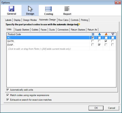 |
The preferred parts list is simply a list of the product codes of the parts that you wish the program to try using first. Each item has a checkbox for each design mode, so you can control which parts are used for which type of design. You can edit this list by hand, or drag-and-drop parts from the Parts catalog directly into these lists. (Hold down the [Alt] key if you want to add or create an item with only the current design mode checked, otherwise a part will be used in all design modes by default). If you drag-and-drop a part from the Parts catalog, each section will only accept the correct type of part. For example, you can drop a unit into the Units section, but not into the ducts section. You can however make any edits you wish (even incorrect ones) by hand. See the Options section for a complete description of the design options in this dialog.
Note in particular that an outlet is a part that connects directly to a duct, such as a neck adaptor or MDO. Don't confuse an outlet with a face, which is typically a grille and is independent of the size of the duct.
The order that you specify the product codes in these lists is important. The program will use the first suitable part that it finds in the list. You can reorder the list by dragging any item up or down. If a part of the size and function that the designer requires is not present in the preferred parts list, the program will next search in your Favourites for it. Your favourites are marked by a star icon in the parts catalog:
 |
If the required part cannot be found in your favourites, the program will then search through all of your loaded catalogs for a suitable part as a last resort.
You should configure the Automatic Designer settings (or at a minimum, your Favourites) before using the designer, or else you may get unusual results. If the program resorts to searching all your catalogs for a required part, you are likely to get a design made up of unusual or inappropriate parts.
The parts used are sized according to the duct size flow rate limits in the preceding Flow Calcs tab.
Same Sized Outlets
The Automatic Design -> Outlets tab also has an option Make outlets same size within region to force all the outlets within one region to be a single, consistent size.
Resultant Flows
The resulting air flow in any part due to the design is shown in the status bar when the part is selected, or by selecting a part and going to the context menu item Properties. Flows are calculated on the assumption that they are balanced to provide the required airflow rates to the zones.
Specifying a Partial Design
You can add and position your own fan coil unit, starter sets, return air boxes and / or outlets in your design before using the Automatic Design tool. The program will try to use the pre-placed components you have already added in its design. It will not use pre-placed duct work or other connectors.
Completing a Design
Once the program has laid out the unit and outlets, you will still need to arrange the parts into their correct final positions
to complete the design (the automatic designer has no knowledge of the underlying building layout, and often outlets can be rearranged
to give a cleaner design). The program will also report any errors or connections that could not be made for any reason, and these should be
fixed manually. You can use the Check Connections toolbar tool ( )
to quickly locate any broken connections. The designer does not guarantee an optimal design, but will usually provide a good starting point
for you to use to complete your design.
)
to quickly locate any broken connections. The designer does not guarantee an optimal design, but will usually provide a good starting point
for you to use to complete your design.
Automatically Adding Joiners
You can use the Toggle Joiners ( ) toolbar tool to automatically
add joiners between duct lengths (marked by a red line) where required, or to remove joiners from ducts that have them (as it's often easier to manipulate lengths of duct
that don't have joiners). The tool applies to any ducts in your current selection, or if nothing is selected, it will apply to all
ducts on the canvas. You need to have a catalog loaded that has joiners in it for this function to work.
) toolbar tool to automatically
add joiners between duct lengths (marked by a red line) where required, or to remove joiners from ducts that have them (as it's often easier to manipulate lengths of duct
that don't have joiners). The tool applies to any ducts in your current selection, or if nothing is selected, it will apply to all
ducts on the canvas. You need to have a catalog loaded that has joiners in it for this function to work.
Go back to How do I?