Plandroid - Graphical Air Conditioning Design and Quoting Software
Plandroid Help Documentation
Calculating the Required Flows
Any load zone that you draw in the canvas in an air-based design mode will have some required air flow. The amount of air required will be determined from the geometry of your zone plus your program settings specified in the Tools -> Options settings under Required air flow:
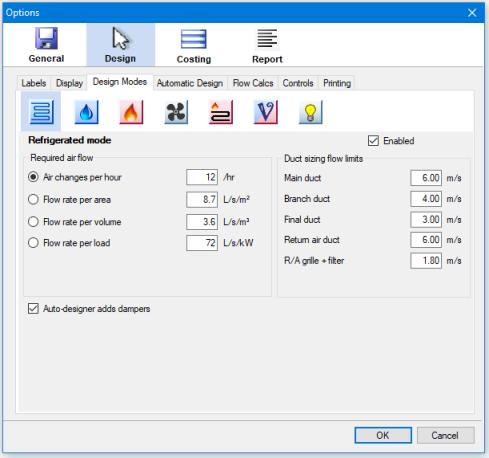 |
For each design mode, you can select from a number of different ways to calculate the required air flows. If the method you have chosen is based on the volume of the air space (namely, Air changes per hour or Flow rate per volume) then the Design -> Loads -> Ceiling height setting will be active, so that when you draw on a zone, you will also be defining a volume for that zone.
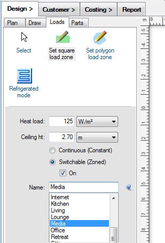 |
If you are designing for a space that does not have a constant ceiling height, such as a raked ceiling or a split-level room, then simply set the average ceiling height.
The program can then calculate the required air flow for each zone, which you can see either in the zone's label, or in the status bar when you select that zone.
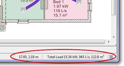 |
Any design you create should supply enough air flow to satisfy these requirements.
Using the Airflow Solver
The Airflow Solver is used to estimate the amount of air moving through the part components placed on your canvas from a fan coil (for example) to some outlets
in order to provide the required air flows.
Air flow calculations are carried out whenever you open the Load Zones Table ( ),
when you press the Solve button in that window, or when
you press the Solve Air Flows toolbar button (
),
when you press the Solve button in that window, or when
you press the Solve Air Flows toolbar button ( ).
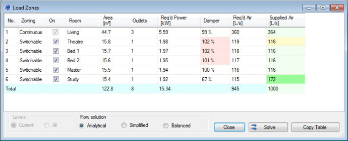
The Load Zones Table will show the total air supplied to each zone, assuming that the air conditioning unit that you have connected
is working at 100% capacity. Zones that are switched off do not receive any airflow. Air can also flow through ducts that connect
between different levels through penetrations. (The Ventilation design mode (
).
The Load Zones Table will show the total air supplied to each zone, assuming that the air conditioning unit that you have connected
is working at 100% capacity. Zones that are switched off do not receive any airflow. Air can also flow through ducts that connect
between different levels through penetrations. (The Ventilation design mode ( ),
Hydronics design mode (
),
Hydronics design mode ( )
and the Lighting design mode (
)
and the Lighting design mode ( ) do not allow solving for airflows, and indeed have custom Load Zones Table layouts).
The Damper column shows an estimate of how open a damper controlling the flow to each zone should be to get the required flow. This figure is shown in red when the damper would need to be opened above 100%, which is not possible.
 |
While the total flows to each zone are shown in the Load Zones Table, you can also investigate the flow in each individual part. The airflow calculations must be carried out
prior to investigating the system, otherwise no results will be shown. The resulting airflows will be shown in the status bar description of any selected part. The context menu
Properties tool will also show the air flow in any part that is transporting air, and will show the face flow velocities of any air inlet or outlet. The Check Design
toolbar button ( ) will show if adequate air is supplied to each zone, if you are on the Plan, Draw, or Loads tab.
Note that you can also show the air flow through a part in its label by including dynamic tags in its label.
There are a range of user-defined parameters that control how the air flow calculations are done in the Flow Calcs section of the Options settings.
Analytical (Accurate) vs. Simplified or Balanced (Fast) Solutions
The program supports three different solution methods: analytical, simplified and a balanced method. The analytical and simplified solutions simulate an unbalanced design, while the balanced method simulates a perfectly balanced design.
Analytical
The analytical method does a full flow analysis including calculating indicative pressure drops along the flow path. This method assumes that the unit is operating at maximum power and that the design has not been balanced. The calculations required for the analytical solution are quite complicated and can take a significant length of time to perform, but they result in a more accurate solution. The numerical parameters used for this solution can be set in the Options section. An analytical result is still just an estimate, because of the large number of variables in an actual installation.
Simplified
The simplified solution allocates outflows based solely on the relative outlet areas, does not take into account the pressure loss of the system, and is therefore much faster but less accurate. This method also assumes that the unit is operating at maximum power and that the design has not been balanced.
Balanced
The balanced solution mode allocates exactly the required flow to each part, as if the system is running at the exact flow rates required for each zone, and all branches have been balanced correctly. In this mode, the actual flow rate output of the unit is not used. This is also a fast solution.
Because the analytical airflow calculations can be time consuming, calculations are only carried out when you explicitly request them. If you change your design or your geometry, or turn any zones on or off, the airflows will change, and you should recalculate the airflows using either the Solve dialog button or the Solve Air Flows toolbar button before investigating them.
Assumptions
- Zones that are switched off do not receive any airflow.
- Ducts or outlets that do not connect to anything are assumed to be blocked.
- An A/C unit, evaporative unit or heater acts as the fan supplying air to a duct system. A unit or fan is required for the system to transport air.
- Inline fans do not increase airflow or air pressure (except in the Ventilation design mode).
- Where unit performance data is unavailable, the performance characteristic of the unit fan is assumed fixed regardless of the system pressure drop. Where performance data is available, the fan output is a function of the pressure drop.
- The A/C unit is assumed to be operating at 100% power for both analytical and simplified flow solutions.
- Dampers are assumed to be fully open at all times. The estimated damper settings are not used in the flow calculations.
- The calculated pressure drop through a part with multiple outlets is independent of the position of the outlet, that is, all outlets from a single part are given the same pressure drop.
- Pressure drop due to the length of ducting is calculated, but the pressure drop due to the curvature of the duct is ignored. It is best practice to avoid bending ducts through sharp angles in any case.
- Flexible duct is assumed to be fully extended.
Notes
- A plan level can have multiple systems, but each zone can only be supplied by one ducted A/C unit at a time.
- Wall units, cassette units, and bulkhead units however can also be added to any zone, and their cooling capacity will be added to that provided by the ducted system.
- Direct duct connectors such as joiners do not incur any pressure drop.
- Reducers must only be used to reduce the duct size. Placing reducers backwards (as expanders) will give incorrect results.
- Pressure drops due to the additional lengths of rise points and penetrations are included, as are losses due to two 90° elbow bends for each.
- Rigid duct components can have more detailed pressure drop calculations performed, depending on the part's geometry.
- The spacing of branches on drawn rigid ducting is taken into account when calculating pressure drops.
Technical Notes
- The pressure drop through a rigid conduit part can be specified directly in the catalog as an effective length increase. If a part has no effective length specified, the pressure drop is calculated using a fixed loss coefficient in the pressure loss equations.
- Parts that have a function equal to "collar" or "joiner" have no default pressure drop.
Automatically Sizing Ducts to the Required Flow
The Auto-size Ducts toolbar tool ( ) will do two things: it will calculate the duct flows that are required to supply the specified
zone requirements (regardless of the output of your selected unit), and it will then automatically size the ducting to handle that flow.
Your ducting will be sized according to the Duct sizing flow limits specified in the Options section.
) will do two things: it will calculate the duct flows that are required to supply the specified
zone requirements (regardless of the output of your selected unit), and it will then automatically size the ducting to handle that flow.
Your ducting will be sized according to the Duct sizing flow limits specified in the Options section.
Ducting that supplies zones that are switched off is not resized, if that is consistent with the design. You can investigate your system flows after using this tool, in which case you will be shown the required flows, and not the flows due to the output of your A/C unit.
Go back to How do I?