Plandroid - Graphical Air Conditioning Design and Quoting Software
Plandroid Help Documentation
Design Principles
Design Goals
A "good" duct design is one that reaches a suitable balance between a number of (sometimes competing) requirements, namely:
- Suitability for the application
- Reliability, which affects the system's maintenance cost
- Manufacturing or capital costs
- Pressure loss, which affects the system's operating cost
- Air balancing, which affects the commissioning cost
- Acoustics, which is an environmental cost
The parameters that you use in Plandroid will determine how these requirements are balanced in a design made by the program.
General Design Principles
With all ducted air system designs, you should try to follow some general principles and best practices. These principles lead to systems that are most cost effective to build and to run:
- Try to keep your duct runs as short as reasonably possible, to minimise both material costs and running costs.
- Avoid sudden changes in duct directions. Changing the direction of air results in pressure losses and higher running costs.
- Minimise noise and transmitted vibrations. Nobody likes noise, and vibrations can shorten the lifetime of your equipment.
- If you have to turn air in rigid ducting, use turning vanes in your equipment wherever you can.
- For rigid ductwork, try to keep the duct aspect ratio as close to 1 as possible, and no more than 4.
- Reduce pressure losses wherever possible – but balance this with power costs, material costs, and the installation space available.
Commercial Considerations
Real-world installations have an implicit tension between price and performance, especially when you are competing for jobs against other companies in a price-sensitive market. If you are quoting a correctly sized design, but competing for the job against undersized but cheaper designs, you can use Plandroid to demonstrate to your customers what the consequences of an inferior design are.
Creating a Design in Plandroid
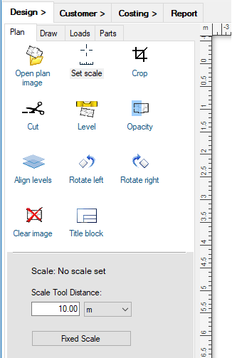
Open And Scale Your Floor Plan Image
To make a design, you usually first open a floor plan image with the Design -> Plan -> Open plan image button.
Then you immediately set the image scale, in one of two ways. If you have dimensions on your plan, you can use the Plan -> Set scale tool ( ). Otherwise, if you already know the scale of the plan, you can use the Fixed Scale button to set the image scale directly.
 |
If you don't have an image, or want to modify the design on the image, you can sketch a plan with the drawing tools in the Design -> Draw toolbox.
Make Sure You Are Working With The Right Catalogs
If you haven't used the program before, you need to make sure you are using parts from your own suppliers, by loading the right set of catalogs. Go to the menu item Tools -> Select Catalogs and check the catalogs you want to use. It helps to be somewhat familiar with the catalogs available, as some catalogs have parts that are specific for particular design modes, and there are special catalogs for making rigid duct designs, or for adding custom cost items, for example. You'll normally need to have at least one parts catalog, and one units catalog loaded, but it is usually a good idea to at least have the symbols catalog loaded, as well as the generic starter sets catalog in case your supplier does not have the correct starters you need.
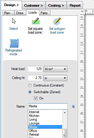
Set Your Load Zones
Next, on the Loads tab, you define what type of system you want
to design by choosing the design mode - refrigerative ( ), evaporative (
 ), etc.
This will determine how the required airflows are calculated, and the options the user interface will present you with.
You specify the load zones themselves by using the Set Load Zone tools also on the Loads tab. Heat loads can be specified
either as a load per area or a load per volume. To choose a load per area, set the heat load units to be based on area (for example kW/m²).
To choose a load per volume, set the heat load units to be based on volume (for example kW/m³).
The heat load can be adjusted individually for each zone. Alternatively, by using the context
menu item Set zone load on a zone you can set its total load directly, regardless of the size of the zone.
), etc.
This will determine how the required airflows are calculated, and the options the user interface will present you with.
You specify the load zones themselves by using the Set Load Zone tools also on the Loads tab. Heat loads can be specified
either as a load per area or a load per volume. To choose a load per area, set the heat load units to be based on area (for example kW/m²).
To choose a load per volume, set the heat load units to be based on volume (for example kW/m³).
The heat load can be adjusted individually for each zone. Alternatively, by using the context
menu item Set zone load on a zone you can set its total load directly, regardless of the size of the zone.
 |
Remember that it is often a good idea to adjust the heat load setting you are using depending on the location of the building, and also between zones depending on each zone's exposure, insulation and window size, for example.
Each separate zone will have its own zone motor (for refrigerative designs). Remember that you can lay out your zones first
and join them together later with the Join Zones toolbar tool ( ).
If you join zones, the program will remember the original zone areas and make sure they each get their own outlets, even if they
share a common zone motor.
).
If you join zones, the program will remember the original zone areas and make sure they each get their own outlets, even if they
share a common zone motor.
If you are making a day / night system, so that you can use a smaller sized unit and therefore have a more cost-efficient design, you will want to turn some zones off by de-selecting the On checkbox.
Lay Out Your Design
Once you have your load zones defined, you can add parts to the canvas to complete your design. From the Design -> Parts tab you can add parts to the design from any of the loaded catalogs you are using. The parts are divided into three levels - the part type at the top, the part sub-type in the middle, and the actual sized parts on the bottom level. Only the actual sized parts (from the bottom window) can be added to the canvas.
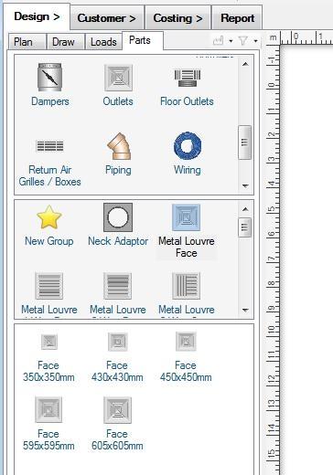 |
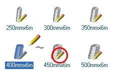
Simply drag and drop parts from the bottom window of the Parts catalog into the design canvas, and then select and move (or rotate) them into their correct places. If the part you are adding to the canvas can snap-to any other part already in your design, any matching connectors will be shown in green. Compatible connectors on the existing parts will also be shown in green, and incompatible connectors will be shown in red. If a part will snap-to a connection if dropped at that point, its connector will glow in green. User-drawn parts, such as ducting, piping, and wiring can be drawn directly onto the canvas with special draw tools. Draw tools are selected by clicking on their icons in the Parts catalog - you can tell a part has a special draw tool associated with it if its icon has a pencil overlay, as shown:
 |
Other overlay images will tell you if the part is not drawn when you print your design
( ), or if the part will add any other parts
automatically once you add it to the canvas (
), or if the part will add any other parts
automatically once you add it to the canvas ( ).
).
You can also get the program to lay out a design for you by using the Automatic design toolbar tool ( ). This will automatically lay out the required outlets and the sized unit to use. However, you do
need to set this tool up by telling the program which parts you want to use by preference. There are some subtleties in
using this powerful tool, so it is well worth looking through the Automatic Design
section for complete instructions on using this function.
). This will automatically lay out the required outlets and the sized unit to use. However, you do
need to set this tool up by telling the program which parts you want to use by preference. There are some subtleties in
using this powerful tool, so it is well worth looking through the Automatic Design
section for complete instructions on using this function.
Using Rigid Ducting
If you are making a design with rigid ducting, you can set the dimensions of any rectangular duct section with the context menu item Set Duct Dimensions for constant runs, or Edit Rigid Connector for any more complicated parts. Rigid ducting can be given a material and priced by material use in the program.
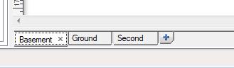
Designing For Multiple Stories
To make a design for a multi-story building, simply use the blue "+" Add level button at the end of the plan level tabs row. This will add a new plan level to your design, and you can add Penetrations between levels to pass duct from one level to another.
 |
These steps are all described in detail in the Design page section.
Evaluate Your Design
Once you have created your design, you can analyse the air flows in your existing duct layout with the
Solve Air Flows tool ( ), or have
the program automatically size the ducting for you according to your zone requirements using the
Auto-size Ducts tool (
), or have
the program automatically size the ducting for you according to your zone requirements using the
Auto-size Ducts tool ( ).
You can also check your design for possible missing connections or inadequate air flows with the Check Zones and Connections
tool (
).
You can also check your design for possible missing connections or inadequate air flows with the Check Zones and Connections
tool ( ).
).
Go back to How do I?