Lighting Design Mode

Lighting Systems
Modern lighting systems require a systematic design that properly accounts for the amount of light supplied to different rooms based upon their use. In addition, the amount of electrical power that is used for lighting should be maintained within set bounds for environmental reasons. Normally a lighting system should be designed so that no more than 5 W/m² is used on average over the premises.
Designing a Lighting System
You can select the lighting design mode ( ) with the
Design -> Loads -> Design mode drop-down button.
) with the
Design -> Loads -> Design mode drop-down button.
You should ensure that you have loaded suitable catalogs that include lights, switches, wiring, and other electrical components when you do a design in the lighting design mode.
Required Lighting
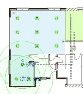
When you lay out a zone in the lighting design mode, you specify the illuminance that the zone requires. The illuminance is the total luminous flux incident on a surface, per unit area. It is a measure of how much the incident light illuminates a surface, adjusted to human brightness perception, and has the units of lux (lx). Different living areas require different levels of illuminance: a workshop may require 400 lx, while a hallway may only require 40 lx. When you lay out zones in the lighting design mode, the program will keep track of how much lighting is required, and how much has been supplied by any lights you have added, so you can immediately see if you have added a sufficient number of lights to achieve your requirements. The running totals are reported in the status bar, including the average electrical power used over the premises.
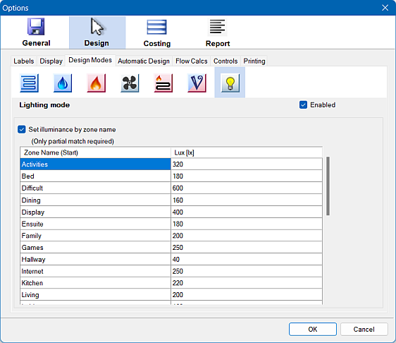
The lighting design mode settings under Options -> Design -> Design Modes -> Lighting mode allow you to specify the illuminance required for any room based on its name. If you enable this option, Plandroid will automatically set a user-defined lighting level for each zone as you draw it.
Connecting Lights
Electrical components are, naturally, connected with wires. You can change how a wire is drawn by right-clicking on it to bring up the context menu and selecting a Draw Style from the available options. Note that wires are the only part whose properties are affected by its draw style. The wire length will be calculated differently for each style, to match how it is drawn: as arcs, as straight lines, or as rectangular lengths.
Some lights are designed to have a single wire connecting them to a controller, while other lights are designed to be linked together in a chain with one or more switches or controllers in the group. This should be clear from your supplier's catalog.
Aligning Lights
The Plandroid toolbar tool Adjust Position ( )
toolbar has submenu items Align to Grid and Resize Grid, which are useful for rearranging groups of lights into a regular
ceiling layout.
)
toolbar has submenu items Align to Grid and Resize Grid, which are useful for rearranging groups of lights into a regular
ceiling layout.
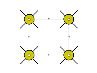
Also, if you have selected 3 or more parts, you can toggle between rotation or layout resizing of the selection with the R key.
Light Throw Circles
If you are in the lighting mode you can use the T shortcut key to toggle the display of the lights' throw circles. The throw circle is a circle on the floor that indicates the region under the light where the light is at 50% of its centreline intensity. It is based on the light's beam angle and the ceiling height of the zone it is in. A light will only have a throw circle if it is in a zone.
Light Groups
Lights that will be controlled by the same switch should be stringed or grouped together by connecting them together with the same wire. Lights can be grouped together by physical wires or by Wi-Fi. You should indicate Wi-Fi groups by connecting the lights with a wire that is a symbol and does not represent any physical hardware.
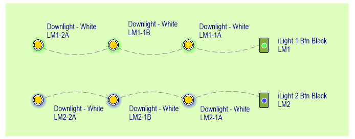
Lights will normally be drawn with a coloured glow halo, which will be the same colour for lights that are grouped together. Once a light is connected to a controller or another light it is grouped with that part and will share the same halo colour. For normal controllers, grouped lights indicate that they will all be controlled by one switch on that controller. iZone switches have special behaviour and all the light groups that are controlled by that switch will use the same halo colour.
Naming Lights
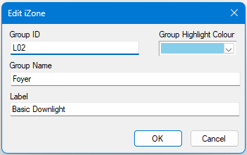
Lighting groups that are connected to an iZone switch can have a group name. If that is applicable, you can set the group name and other properties (such as the group halo colour) by editing the part label of any item in the group. (Double clicking the label is a shortcut to editing the label). Any edits you make to the group properties will then be applied to all items in the group.
Lights that are not connected to an iZone switch will be automatically given unique label identifiers.
Lights that are not connected but should be will show that they are not connected in their label.

Tabulating Your Lighting Data
The lighting mode also has a dedicated zones table layout. By using the toolbar tool Toggle Zones Table
( ) you can display a summary of the lighting information for each
zone in your design. You can also insert a dedicated lighting table in your Report document
by inserting a Zones Table (Lighting) insert item.
) you can display a summary of the lighting information for each
zone in your design. You can also insert a dedicated lighting table in your Report document
by inserting a Zones Table (Lighting) insert item.
Ordering a Lighting System
When placing an order with your manufacturer that includes a lighting design, some manufacturers
require a lighting configuration table to be provided with the order. If that is the case, the additional toolbar button
Export Lighting Table ( ) will show on the toolbar,
which will allow you to preview the configuration table as a CSV file. The configuration table will summarise how the lights
and switches should be wired up to reflect your design, and will normally be sent as an additional file with your order.
) will show on the toolbar,
which will allow you to preview the configuration table as a CSV file. The configuration table will summarise how the lights
and switches should be wired up to reflect your design, and will normally be sent as an additional file with your order.
The lighting design mode is not currently supported by the Automatic Designer.
An additional lighting licence module is required to use this mode.