How Do I Make a Design?
Design Principles
Design Goals
A "good" duct design is one that reaches a suitable balance between a number of (sometimes competing) requirements, namely:
- Suitability for the application
- Reliability, which affects the system's maintenance cost
- Manufacturing or capital costs
- Pressure loss, which affects the system's operating cost
- Air balancing, which affects the commissioning cost
- Acoustics, which is an environmental cost
The parameters that you use in Plandroid will determine how these requirements are balanced in a design made by the program.
General Design Principles
With all ducted air system designs, you should try to follow some general principles and best practices. These principles lead to systems that are most cost effective to build and to run:
- Try to keep your duct runs as short as reasonably possible, to minimise both material costs and running costs.
- Avoid sudden changes in duct directions. Changing the direction of air results in pressure losses and higher running costs.
- Minimise noise and transmitted vibrations. Nobody likes noise, and vibrations can shorten the lifetime of your equipment.
- If you have to turn air in rigid ducting, use turning vanes in your equipment wherever you can.
- For rigid ductwork, try to keep the duct aspect ratio as close to 1 as possible, and no more than 4.
- Reduce pressure losses wherever possible – but balance this with power costs, material costs, and the installation space available.
Commercial Considerations
Real-world installations have an implicit tension between price and performance, especially when you are competing for jobs against other companies in a price-sensitive market. If you are quoting a correctly sized design, but competing for the job against undersized but cheaper designs, you can use Plandroid to demonstrate to your customers what the consequences of an inferior design are.
Creating a Design in Plandroid
Open And Scale Your Floor Plan Image
To make a design, you usually first open a floor plan image with the Design -> Plan -> Open plan image button.
You must set the image scale so the program knows the size of the building before you add any zones or parts. You can do that in two ways. If you have dimensions on your plan, you can use the Plan -> Set scale tool ( ). Otherwise, if you already know the scale of the plan, you can use the Fixed Scale button to set the image scale directly.
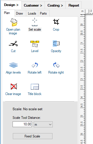
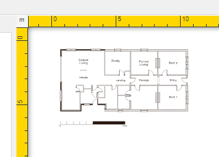
Once you have scaled your floor plan, the rulers will change from yellow to grey to show you that you can continue.
If you don't have an image, or want to modify the design on the image, you can sketch a plan with the drawing tools in the Design -> Draw toolbox.
Load The Right Set of Catalogs
If you haven't used the program before, you need to make sure you are using parts from your own suppliers, by loading the right set of catalogs. Go to the menu item Tools -> Select Catalogs and check the catalogs you want to use. It helps to be somewhat familiar with the catalogs available, as some catalogs have parts that are specific for particular design modes, and there are special catalogs for making rigid duct designs, or for adding custom cost items, for example. You'll normally need to have at least one parts catalog, and one units catalog loaded, but it is usually a good idea to at least have the symbols catalog loaded also, as well as the generic starter sets catalog in case your supplier does not have the correct starters you need.
Choose Your Heat Load Method
Heat loads can be specified as a Zone Based Loads, or the program can calculate them from the specified material properties, building layout, and weather conditions depending on the heat load method selected. You chose which method you will use and specify the other settings that you need with the menu item Heat Load.
The zone Area Load method is the quick and simple option — just enter a load value per area (or volume) for the zone, and you’re done.
The ACCA Manual J8 method is a materials-based method which is far more comprehensive. The program calculates heat loads automatically from your specified material properties, building layout, and local weather conditions — a much more involved process, but one that produces a more accurate and robust result.
The method you select determines the effort you need to put into specifying the further details of your drawing.
Draw Your Walls and Add Windows and Doors
If you are using a materials-based heat load method, you need to go to the Draw tab and use the tools there to draw in your building layout. Use the Draw room, Draw wall, Add window and Add doors tools and set the materials used. Also set the orientation by adding a compass. If you are using the load per area load method, these steps are optional because the material properties are not used to calculate the loads.
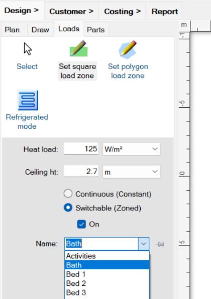
Set Your Load Zones
Next, on the Loads tab, you define what type of system you want
to design by choosing the design mode - refrigerative ( ,
,  , or
, or  ), evaporative (
 ), etc.
This will determine how the required airflows are calculated, and the options the user interface will present you with.
You specify the load zones themselves by using the Set Load Zone tools also on the Loads tab. If you have chosen to use heat loads per zone, then you have the option to specify the loads as
either load per area or a load per volume. To choose a load per area, set the heat load units to be based on area (for example kW/m²).
To choose a load per volume, set the heat load units to be based on volume (for example kW/m³).
The heat load can be adjusted individually for each zone. Alternatively, by using the context
menu item Set zone load on a zone you can set its total load directly, regardless of the size of the zone.
), etc.
This will determine how the required airflows are calculated, and the options the user interface will present you with.
You specify the load zones themselves by using the Set Load Zone tools also on the Loads tab. If you have chosen to use heat loads per zone, then you have the option to specify the loads as
either load per area or a load per volume. To choose a load per area, set the heat load units to be based on area (for example kW/m²).
To choose a load per volume, set the heat load units to be based on volume (for example kW/m³).
The heat load can be adjusted individually for each zone. Alternatively, by using the context
menu item Set zone load on a zone you can set its total load directly, regardless of the size of the zone.
Remember that with the per zone heat load setting it is often a good idea to adjust the heat load setting you are using depending on the location of the building, and also between zones depending on each zone's exposure, insulation and window size, for example.
If you are using a materials-based heat load method like Manual J, you will need to specify the material properties of the floor and ceiling of the zones instead of their loads. The program will calculate the resulting loads itself. This is usually a more involved and complicated process as you must specify much more information.
Each switchable (or zoned) zone will have its own zone damper motor. Continuous or constant zones do not require a zone motor. Likewise evaporative designs are not normally zoned. Remember that you can lay out your zones first and join them together later with the Join Zones toolbar tool ( ).
If you join zones, the program will remember the original zone areas and make sure they each get their own outlets, even if they
share a common zone motor.
).
If you join zones, the program will remember the original zone areas and make sure they each get their own outlets, even if they
share a common zone motor.
If you are making a day / night system, so that you can use a smaller sized unit and therefore have a more cost-efficient design, you will want to turn some zones off by de-selecting the On checkbox.
Lay Out Your Design
Once you have your load zones defined, you can add parts to the canvas to complete your design. From the Design -> Parts tab you can add parts to the design from any of the loaded catalogs you are using. The parts are divided into three levels - the part type at the top, the part sub-type in the middle, and the actual sized parts on the bottom level. Only the actual sized parts (from the bottom window) can be added to the canvas.
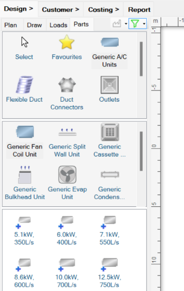
Simply drag and drop parts from the bottom window of the Parts catalog into the design
canvas, and then select and move (or rotate) them into their correct places. Hold down [Ctrl] or [Shift]
if you want to drop the same part into the canvas multiple times by going into multi-drop mode
( ). If the part you are adding to the canvas
can snap-to any other part already in your design, any matching connectors will be shown in green. Compatible
connectors on the existing parts will also be shown in green, and incompatible connectors will be shown in red.
If a part will snap-to a connection if dropped at that point, its connector will glow in green.
User-drawn parts, such as ducting, piping, and wiring can be drawn directly onto the canvas with special draw tools.
Draw tools are selected by clicking on their icons in the Parts catalog - you can tell
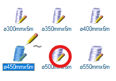
a part has a special draw tool associated with it if its icon has a pencil overlay, as shown:
). If the part you are adding to the canvas
can snap-to any other part already in your design, any matching connectors will be shown in green. Compatible
connectors on the existing parts will also be shown in green, and incompatible connectors will be shown in red.
If a part will snap-to a connection if dropped at that point, its connector will glow in green.
User-drawn parts, such as ducting, piping, and wiring can be drawn directly onto the canvas with special draw tools.
Draw tools are selected by clicking on their icons in the Parts catalog - you can tell
a part has a special draw tool associated with it if its icon has a pencil overlay, as shown:
Other overlay images will tell you if the part is not drawn when you print your design
( ), or if the part will add any other parts
automatically once you add it to the canvas (
), or if the part will add any other parts
automatically once you add it to the canvas ( ).
).
Design From the Outlets Back to the Unit
If you are creating your design manually, you should choose a suitable fan coil unit that has the required cooling or heating capability, as well as sufficient air flow to service the maximum number of zones that you wish to run at one time. Your design requirements are shown in the status bar along the bottom of the program. Place the unit on your floor plan where you will physically locate it in the building. Next, add sufficient outlets of suitable size to your zones to supply the required air flows for each zone. Using the multi-drop mode in Plandroid makes this quick and easy to do. Next connect the outlets back to the unit with ducting, using connectors such as Y-pieces to join the ducts. Add dampers to control the air flow to each zone. Finally add any other parts that you need such as drip trays and controllers, plus any accessories such as mounts and duct tape. Accessories such as tape that are not printed can be placed anywhere on your canvas.
Use Tools to Automate Time Consuming Tasks
Plandroid has many tools for helping you speed up the design process and to ensure that your components are
sized correctly. Use the keyboard key `~ to toggle the Quick Build tool ( ) on and off. This tool lets you draw your common parts straight onto your design without going back to your Parts catalog. Use the Auto-size Outlets tool (
 )
to automatically size the ducting you have drawn yourself according to the required air flow for each zone.
Alternatively you can get the program to lay out an entire design for you by using the Automatic design toolbar tool (
)
to automatically size the ducting you have drawn yourself according to the required air flow for each zone.
Alternatively you can get the program to lay out an entire design for you by using the Automatic design toolbar tool ( ). This will automatically lay out a basic design using the correctly sized unit, ducting, and outlets for your zones.
You only need to move the parts around into their final positions to complete your design. However, you do
need to set this tool up by telling the program which parts you want to use by preference. There are some subtleties in
using this powerful tool, so it is well worth looking through the Automatic Design
section for complete instructions on using this function.
). This will automatically lay out a basic design using the correctly sized unit, ducting, and outlets for your zones.
You only need to move the parts around into their final positions to complete your design. However, you do
need to set this tool up by telling the program which parts you want to use by preference. There are some subtleties in
using this powerful tool, so it is well worth looking through the Automatic Design
section for complete instructions on using this function.
Take Care to Place Outlets Inside Zones
If you are manually adding outlets to your zones, take care to ensure that each outlet is located inside the appropriate zone. The program will only count outlets that are located inside the zone as supplying air to that zone. Placing a linear slot diffuser next to the zone it is supplying air to — but not inside the zone — will not supply air to that zone.
Using Rigid Ducting
If you are making a design with rigid ducting, you can set the dimensions of any rectangular duct section with the context menu item Set Duct Dimensions for constant runs, or Edit Rigid Connector for any more complicated parts. Rigid ducting can be given a material and priced by material use in the program.
Designing For Multiple Stories
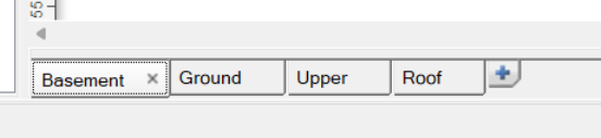
To make a design for a multi-story building, simply use the blue "+" Add level button at the end of the plan level tabs row. This will add a new plan level to your design, and you can add Penetrations between levels to pass duct from one level to another.
These steps are all described in detail in the Design page section.
Check Your Design
You can do quick checks of your design for possible missing connections or inadequate air flows with the Check Zones and Connections
toolbar tool ( or press C).
You can do more detailed design checks with the built-in design check tool. If the program has identified any design errors that need to be fixed it will show that in the status bar.
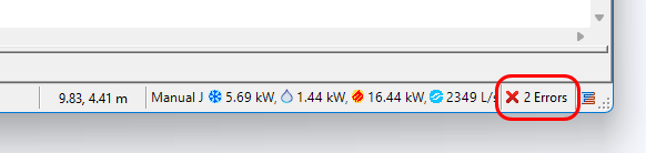
Always keep an eye on these errors to make sure you haven't missed anything important that could give you incorrect results.
Evaluate Your Design
Once you have created your design, you can analyse the air flows in your existing duct layout with the
Solve Air Flows tool ( ).
).
It is always a good idea to check your airflows per zone by opening the Load Zones table with
the Toggle Zones Table toolbar button ( ).
).
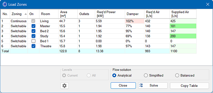
This table lets you check you have adequate air flow to your zones, and lets you see how turning various zones on and off influences the resulting airflow.
If you have done a detailed heat load calculation, you can generate a detailed heat load report.