Manual J Heat Loads
Manual J is a building standard that takes the building location, orientation, construction style, insulation, and building materials into account when generating a heat load, which is a much more accurate method than using a rule of thumb area-based method. Manual J also takes into account the fact that thermal masses will shift peak loads, and that coincident peak loads are not additive in practice - eastward facing walls, roof loads, and westward facing walls will all reach solar peak loads at different times of the day. It produces load estimates that are targeted to be exceeded 1% of the time, instead of designing for the worst day ever recorded. For all of these reasons, Manual J will typically produce significantly lower load estimates than rule of thumb methods, which leads to selecting more economically sized equipment.
Manual J is primarily designed for calculating residential heat loads for buildings in the United States and Canada, following ASHRAE and ACCA (Air Conditioning Contractors of America) standards. However it can also be used in other countries. Manual J has a number of limitations and is not suitable for all situations. It requires detailed inputs and assumes that you understand the methodology and have been trained in its use.
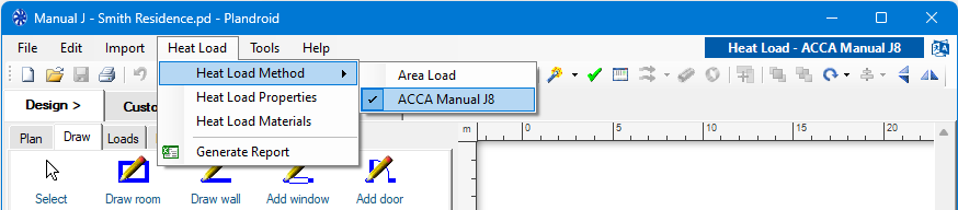
To carry out Manual J heat loads in Plandroid you need to use the menu item Heat Load -> Heat Load Method -> ACCA Manual J8. (Plandroid implements the standards from the 8th edition of Manual J).
Properties
To do a Manual J heat load calculation you will first need to use the menu item Heat Load -> Heat Load Properties to specify the location climate data and other values specific to this design that will be used to perform the load calculation.
Materials
The menu item Heat Load -> Heat Load Materials lets you customise the selection of materials you want to use as your local material library when doing a Manual J heat load design. The dialog will display all of the material properties that will be available in the Design -> Draw material selection drop-downs. You can edit this selection to suit your own needs by adding to it from the wide selection of pre-defined materials available in Manual J, removing materials that you do not use, or by adding your own custom material definitions.
Set North
Open and scale your floor plan image if you have one, and then use the Design -> Draw -> Show north tool to add a North marker and set its angle to specify the orientation angle of your plan. This is required for calculating the sun incidence angle on the building. In accordance with Manual J, building angles are rounded to one of the eight intercardinal compass points (N, NE, E, SE, S, SW, W, NW).
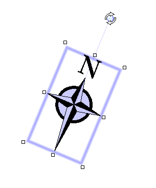
Designs with multiple levels are assumed to be at the same orientation and require only one compass on one level.
Walls, Windows and Doors
Manual J heat load calculations are concerned with the heat flows through the external walls only. All external walls, windows and doors must have a material definition, because that affects the heat flows and must be accounted for. Internal walls do not factor into the calculations, and can be made of any material, including no material (material None).
Use the tools from the Design -> Draw tool tab to draw the building external walls and set the wall materials. Then add the windows and doors and set their materials and properties. Using the correct materials is critical to performing an accurate heat load calculation. The toolbar tool Show Glass Labels ( ) will show the label data for the windows (and any glass doors) and Show Below Grade (
 ) will show the below grade indicators respectively. Select either a wall or its below grade indicator to edit its depth underground.
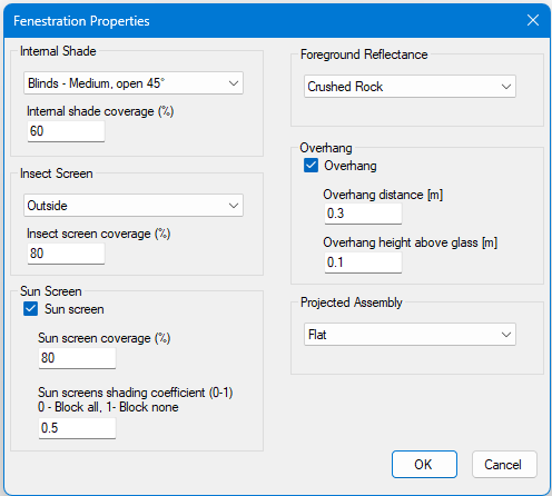
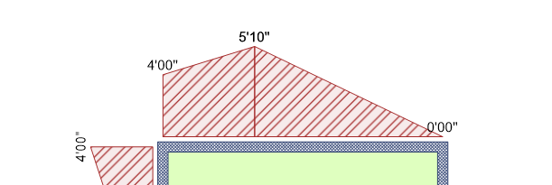
The glass labels show all the Fenestration Properties that define the window diagrammatically so you can see instantly what they are:
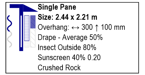
Double click on a label to edit its properties, or use the context menu item Glass Properties. The fenestration properties include the internal shade from drapes and blinds, shading from insect screens and sun screens, the foreground reflectance, the overhang shading, and Projected Assembly settings in case you need to account for bay windows or garden windows. Note the sun screen shading coefficient represents how much sunlight is transmitted, so 1.0 represents full transmission (clear), and 0.0 is no transmission (all light blocked).
Moving the Draw room, Draw wall, Add window, or Add door tool over a corresponding wall, window, or door will convert the tool to an eyedropper. Clicking with the eyedropper tool will copy the wall, window or door's physical and material settings. This lets you quickly reuse the properties of an existing object for the next one you draw.

Below Grade Walls
You can use the wall context menu item Make Below Grade to indicate that the wall is fully or partially underground, or Remove Below Grade if it is not. You can use the handles on the below grade indicators to drag them to the required depth. Double click on a wall to add another handle if you need finer control over the grade profile.
Below grade walls must be given a material that has below grade material properties, as this also includes the thermal properties of the soil the wall is in. You should normally use materials with Construction Number 15 for this.
Editing
Use the context menu item Select All of This Material on any wall, window or door to select all of the items that are made of that material if you want to edit all of them at once.
Zones
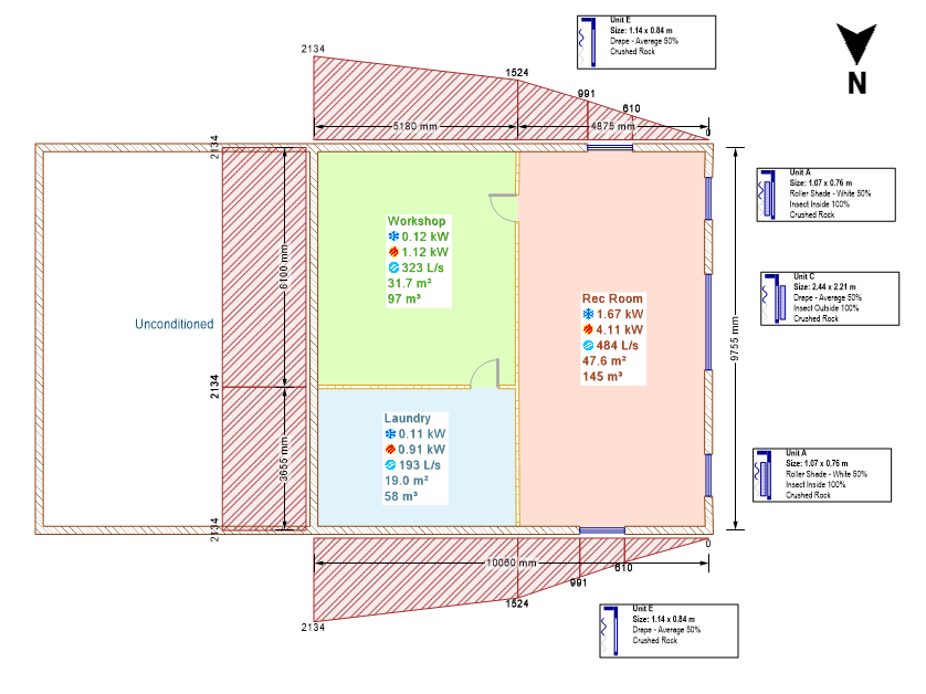
Once you have drawn your walls, you will need to set the load zone or zones using the tools from the Design -> Loads tool tab. This is most easily done with the Fill Rooms tool, but you can equally draw the zones yourself.

You will need to set the material properties of the zone's ceiling and floor when you use this tool. You need to set the zone materials and the wall materials for a zone before a heat load can be calculated. If you haven't set enough materials to calculate the heat load, its heating or cooling requirements will be shown as ??? in the zone's label and in the status bar to indicate this.
While Plandroid lets you set the properties of individual zones, Manual J itself assumes that the entire home has a single, uniform indoor temperature. It does not support multi-zone thermostat controls that regulate different areas independently. It is very important to be aware that you must fill in the entire building with zones when using the Manual J heat load method. Heat transfer is only calculated through walls into zones, therefore your external walls must be completely filled by zones, even if they are unconditioned zones, for the calculations to be accurate. This is fundamentally different to using the basic area loads method.
If you need to specify separate zones that share an open connection, you can draw a door between them and set its draw style to Open Doorway.
Unconditioned Zones
If a zone is unconditioned or is a courtyard, you can use the context menu on the Fill rooms tool to mark a room as such. It will then be excluded from the building load calculation.
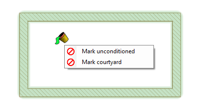
Unconditioned spaces are typically garages, attics, crawl spaces or mechanical rooms. Courtyards are open air spaces that are directly exposed to the outdoor environment. To remove the mark, simply delete the text in the zone marking it and it will return to a conditioned space.
Zone Occupant Loads
In Manual J, the number of occupants in a building is calculated as the number of bedrooms plus 1. Zones that have names that begin with "Bed" will automatically be counted as bedrooms and will therefore add an occupant which is counted in the occupant loads.
Additional Loads
We do not currently support adding additional loads such as machinery or electrical equipment beyond the standard Manual J internal load scenarios.
Skylights
We do not currently support adding the heat loads from skylights.
Checking Your Design
It can be complicated to be sure you have all the data correctly in your design. To help with this Plandroid has a built-in design checker that can give you feedback on the state of your design and give you guidance on how to make corrections. The design checker is shown in the bottom right corner of the program window.
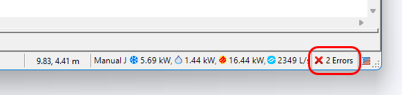
Click on the design checker to view any design issues - warning or errors - that have been identified in your design. In the Design Issues dialog you have the option to see what fixes are available, to ignore the issue, or to open the appropriate help documentation on the item. Make sure you have addressed all of the issues identified before you commit to your design.
Totals
Note that unlike the Zone Based Loads heat load method, the totals shown in the status bar for Manual J loads when no zones are selected do not generally sum to the total of each individual zone. This is because the total will include loads such as duct loads that are applicable to the design as a whole but do not appear in any individual zone.
Northern Vs. Southern Hemispheres
Although Manual J is designed for the Northern hemisphere, Plandroid supports working in both Northern and Southern hemispheres. If you choose your design conditions location to be in the Southern hemisphere, the program will adjust for the seasonal differences and sun location so that the calculations reflect your location accurately.
Manual J Reports
Once you have finished your design, you can use the menu item Heat Load -> Generate Report to create a complete Excel workbook showing all the calculations the program has performed to obtain the resultant heat loads. The report is laid out in the standard ACCA Manual J format. Naturally you need to have Microsoft Excel installed to use this function. Small discrepancies between hand-calculated heat loads and those calculated by Plandroid are normal, as the program performs more precise data interpolations and avoids some shortcuts that simplify manual calculations but are not required in software.
The workbook includes the Form J1 as well as the component work sheets A to I and the location hourly load curves.
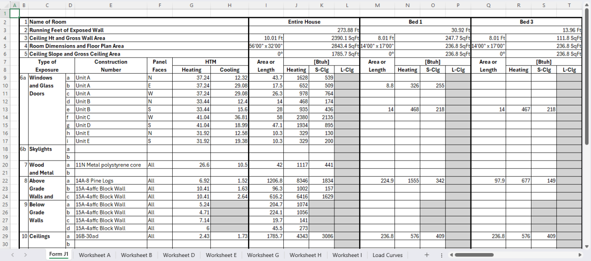
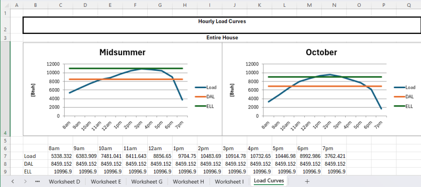
The Form J1 is always made, but a separate heat loads licence module is required to generate any of the component worksheets or the hourly load curves.